Industrial chillers serve as the primary thermodynamic engine in modern mission-critical infrastructure—from hyperscale data centers and pharmaceutical synthesis suites to semiconductor cleanrooms, chemical synthesis reactors, and district cooling networks. In these high-intensity facilities, uninterrupted thermal stability is non-negotiable; an uncontrolled temperature excursion of just 1.5°C can compromise ISO 14644 cleanroom certifications, trigger automated server CPU thermal throttling, or spoil millions of dollars in temperature-sensitive biopharmaceutical batches. Yet, chillers also represent the single largest electrical consumer in most industrial mechanical plants, routinely accounting for 35% to 50% of a facility’s aggregate power consumption.
The operational efficiency of any vapor-compression chiller is fundamentally dictated by its ability to transfer thermal energy across phase-change boundaries in the evaporator and condenser. From a heat transfer perspective, the overall thermal resistance of a heat exchanger is governed by the classic resistance-in-series formulation:
1 / (U · A) = 1 / (h_i · A_i) + R_{f,i} / A_i + ln(r_o / r_i) / (2 π k L) + R_{f,o} / A_o + 1 / (h_o · A_o)
Where U is the overall heat transfer coefficient (Btu/hr·ft²·°F), Rf,i and Rf,o represent internal and external fouling resistances, k is thermal conductivity of the tube wall, and h represents fluid convection film coefficients.
When heat transfer surfaces accumulate mineral scale, biological slime, particulate fouling, or oil films, the fouling resistance terms (Rf) escalate precipitously. Because copper and aluminum conduct heat at approximately 220 to 118 Btu/hr·ft·°F respectively, whereas calcium carbonate scale (CaCO3) has a dismal thermal conductivity of roughly 1.3 Btu/hr·ft·°F, an ultra-thin fouling layer acts as an insulative thermal jacket. A scale deposit measuring merely 1/16 inch (1.6 mm) forces the compressor to elevate its discharge condensing pressure to reject heat.
Thermodynamically, every 1°F (0.55°C) increase in condensing temperature increases compressor power draw by approximately 1.5% to 2.0% per ton of refrigeration (kW/ton). A 1/16" scale deposit routinely forces condensing temperatures up by 15°F to 20°F above design specifications, generating a staggering 30% to 38% energy consumption penalty. In a 1,000-ton central chiller plant operating 8,000 hours per year at $0.12/kWh, unmitigated heat exchanger fouling squanders over $120,000 annually in parasitic electrical losses while elevating compressor discharge temperatures and accelerating mechanical bearing wear.
Sustaining continuous high-efficiency operation requires transitioning from reactive breakdown troubleshooting to an authoritative, data-driven preventive maintenance protocol. This comprehensive engineering checklist provides facility engineers, HVAC technicians, and plant operators with the technical procedures, parameter thresholds, and diagnostic workflows essential for safeguarding industrial chiller investments.
Daily & Weekly Operational Logging: The First Line of Defense
Effective chiller maintenance begins not with hand tools, but with disciplined operational telemetry logging. Modern microprocessors and Building Management Systems (BMS) track hundreds of sensory inputs; however, human logging and trend validation remain critical to detect sensor drift, mechanical fatigue, and emerging thermodynamic anomalies before safety trips occur.
1. Supply/Return Temperature Differential (ΔT)
Under standard AHRI 550/590 design conditions, water-cooled and air-cooled chillers are engineered for a 10°F chilled water temperature split (e.g., 54°F entering / 44°F leaving chilled water at 2.4 GPM/ton), while contemporary low-flow, high-delta systems operate at 12°F to 16°F splits (e.g., 58°F entering / 42°F leaving). Logging chilled water ΔT under varying plant load profiles exposes the infamous "Low ΔT Syndrome". If the temperature differential collapses to 4°F to 6°F while the chiller runs at partial load, the plant is circulating excessive water without extracting equivalent thermal heat, wasting pumping power and forcing additional chillers online prematurely.
2. Suction and Discharge Pressures & Thermodynamic Saturation
Operating pressures must be continuously recorded alongside saturation temperatures:
- Saturated Evaporating Temperature (SET): Derived from suction pressure using refrigerant-specific pressure-temperature (P-T) relationships (e.g., R-134a, R-513A, R-1234ze, R-410A). Suction superheat must be verified—typically maintained between 8°F and 14°F (4.4°C to 7.8°C) to ensure dense dry vapor enters the compressor while preventing destructive liquid floodback.
- Saturated Condensing Temperature (SCT): Derived from compressor discharge pressure. Condenser liquid subcooling must be logged at the coil or bundle outlet, with target thresholds between 9°F and 15°F (5.0°C to 8.3°C). Inadequate subcooling indicates refrigerant loss or thermal bypass, causing flash gas in the liquid line ahead of the electronic expansion valve (EEV).
3. Approach Temperature Monitoring: The Definitive Fouling Indicator
The single most valuable metric for evaluating internal heat exchanger health is the Approach Temperature. Approach defines the thermal difference between the working fluid leaving the heat exchanger and the saturated phase-change temperature of the refrigerant inside the shell or channels:
Evaporator Approach = Leaving Chilled Water Temp (°F) - Saturated Evaporator Suction Temp (°F)Condenser Approach = Saturated Condensing Temp (°F) - Leaving Condenser Water Temp (°F)
On a newly commissioned or chemically cleaned flooded shell-and-tube evaporator, the approach temperature operates cleanly between 1.0°F and 2.5°F (0.55°C to 1.4°C). If operational logs reveal the evaporator approach drifting above 4.0°F (2.2°C), it provides definitive empirical evidence of heat transfer impediment: either water-side tube fouling, microbiological biofilm accumulation, or an insulative oil film coating the refrigerant-side tube surfaces caused by a failing oil recovery ejector.
Similarly, on water-cooled condensers, the design approach ranges between 1.5°F and 3.0°F. An approach exceeding 4.5°F indicates scale buildup on internal tube walls, low cooling water flow, or non-condensable atmospheric air entrained within the refrigeration circuit.
Heat Exchanger & Microchannel Coil Care
Air-cooled chillers increasingly employ all-aluminum Microchannel Heat Exchangers (MCHE) in place of traditional round-tube-plate-fin (RTPF) copper coils. Microchannel coils utilize flat, multi-port extruded aluminum tubes metallurgically furnace-brazed to folded aluminum louvered fins between parallel tubular manifolds.
Microchannel coils reduce overall chiller refrigerant charge by 30% to 40%, enhance air-side thermal conductance by up to 25%, and reduce dry structural weight. However, their high fin density (typically 18 to 24 fins per inch) creates a dense labyrinth that traps airborne particulates, industrial soot, and biological pollen. Furthermore, the 0.05 mm aluminum fins are structurally vulnerable to deformation, and bare aluminum is amphoteric—reacting aggressively to acidic and alkaline environments.
Standardized Microchannel Cleaning Protocol
To maintain maximum heat rejection without inflicting catastrophic physical or metallurgical damage to aluminum microchannel coils, service personnel must strictly adhere to the following procedural standard:
- Lock-Out/Tag-Out (LOTO) & De-Energization: Disconnect and lock out main three-phase power to the chiller. Verify zero electrical potential across all condenser fan motor terminals. Secure mechanical fan blade rotation to prevent accidental freewheeling.
- Pre-Inspection & Dry Debris Extraction: Inspect both the coil air-inlet and discharge faces. Using an industrial HEPA-filtered vacuum equipped with a soft horsehair brush attachment, gently remove superficial dry leaves, seeds, and insect matter. Alternatively, discharge clean, oil-free compressed air at less than 30 PSI in the opposite direction of normal condenser airflow (from inside the chiller plenum outward).
- Gentle Low-Pressure Hydraulic Washing (≤ 100 PSI): Commercial pressure washers operating at 1,500 to 3,000 PSI must NEVER be brought near a microchannel coil. High-pressure jets will instantly bend the micro-thin aluminum fins flat against the extruded tubes, permanently choking airflow across entire sections of the coil. Utilize standard municipal water pressure regulated to strictly under 100 PSI (6.9 bar) equipped with a wide 40° fan spray pattern.
- Spray Angle Normal to Coil Face: Maintain the spray nozzle strictly perpendicular (90° normal) to the coil face at a standoff distance of 6 to 12 inches (15 to 30 cm). Sweeping the wand at an oblique or acute angle bends the delicate louvers sideways, ruining the microchannel core.
- Chemical Detergent Selection (Strictly pH-Neutral 6.5 – 8.5): Traditional HVAC coil cleaners containing hydrofluoric acid or concentrated sodium hydroxide must never be applied to aluminum microchannels. Strong acids strip the protective aluminum oxide passivating layer, while alkaline cleaners actively dissolve aluminum metal, producing hydrogen gas and severe micro-pitting. Utilize only certified pH-neutral (pH 6.5 to 8.5) biodegradable foaming cleaners specifically labeled as aluminum-safe. Allow the cleaner to soak for 5 to 10 minutes to emulsify oily road grime and organic film.
- Comprehensive Potable Flush: Thoroughly rinse the coil from top to bottom with clean potable water until effluent runoff shows zero detergent foam and runoff pH matches supply water. Any residual chemical crust will attract airborne dust and foster accelerated galvanic corrosion.
In harsh coastal marine environments subjected to continuous airborne ocean salts or industrial processing zones with sulfur dioxide fumes, bare aluminum microchannels require robust specialized barrier protection. Engineers evaluating long-term coil integrity should review our detailed analysis on the advantages of electrophoretic coating (E-Coating) for microchannel heat exchangers, which demonstrates how cathodic epoxy electro-deposition achieves 5x corrosion resistance across dense fin matrices without thermal penalty.
Hydronic Loop & Water Quality Management
The hydronic distribution loop acts as the circulatory system of the cooling plant. Failure to calibrate flow dynamics and maintain precise hydronic chemistry leads directly to tube scaling, biological fouling, and premature pipe erosion.
Chilled Water Flow Rates (Maintaining 2.5 to 3.0 GPM per Ton)
Heat transfer across the evaporator shell or brazed plate bundle requires maintaining the design chilled water flow rate, typically calibrated between 2.4 and 3.0 Gallons Per Minute (GPM) per ton of refrigeration, in accordance with the fundamental hydronic energy equation:
Q (Btu/hr) = 500 · GPM · ΔT (°F) ⇒ GPM / Ton = 24 / ΔT
At a 10°F design delta, flow is 2.4 GPM/ton; at an 8°F delta, flow reaches 3.0 GPM/ton. Maintaining this velocity ensures the fluid operates well inside the turbulent flow regime with a Reynolds number exceeding 4,000 (Re > 4,000). If the flow rate falls below 2.0 GPM/ton, fluid velocity through internal tubes drops below 3.0 feet per second (fps). The boundary layer stagnates into laminar flow, slashing the convective heat transfer coefficient (hi) by over 45% and encouraging suspended silt and particulate matter to settle out onto tube surfaces.
Conversely, flow rates exceeding 3.5 GPM/ton (tube fluid velocity > 8.5 to 10 fps) induce severe mechanical erosion-corrosion, stripping the protective copper oxide film and causing catastrophic tube wall perforation within 3 to 5 years. Flow rates must be verified quarterly by measuring the differential pressure drop (ΔP) across evaporator inlet and outlet Pete’s plugs using a calibrated digital manometer and cross-referencing the manufacturer’s bundle pressure-drop performance curve.
Glycol Freeze Point Calibration via Refractometer
In low-temperature process chillers, ice-storage systems, or air-cooled chillers located in freeze-prone climates, the hydronic loop utilizes inhibited ethylene or propylene glycol. Maintaining the correct concentration is vital:
- Refractometer Testing Only: Never employ floating-ball hydrometers, as specific gravity fluctuates significantly with temperature and fluid age, resulting in errors of up to 15% glycol concentration. Always utilize an optical or digital Brix refractometer calibrated with distilled water at 68°F (20°C).
- Burst vs. Freeze Protection: Differentiate between freeze protection (fluid remains completely pumpable without slush formation) and burst protection (fluid turns to slush but expands without rupturing copper tubes). Standard industrial specifications mandate maintaining freeze protection at least 10°F (5.5°C) below the lowest recorded ambient temperature or lowest evaporator saturated suction temperature.
- Reserve Alkalinity & Thermal Degradation: Glycol naturally oxidizes over time under heat and oxygen exposure, forming acidic organic byproducts (glycolic, formic, and acetic acids). Service technicians must test the fluid’s pH (target: 8.5 to 9.5) and Reserve Alkalinity (RA). If pH falls below 8.0, the inhibitor package is depleted and the fluid must be re-buffered or replaced before acid attack corrodes ferrous pipework and copper coils.
Scale Inhibitors & Microbiological Control
For water-cooled condenser loops, open cooling towers expose cooling water to airborne dust, mold spores, and minerals. If left untreated, calcium and magnesium carbonate precipitate directly onto hot condenser tube surfaces. Water treatment regimes must continuously maintain:
- Conductivity below 1,500 to 2,200 μS/cm via automated bleed-off controllers to limit Total Dissolved Solids (TDS).
- Molybdate (50 to 100 ppm) or Nitrite (800 to 1,200 ppm) passivating corrosion inhibitors for closed chilled loops.
- Dual biocide rotation (alternating oxidizing biocides such as chlorine dioxide or bromine with non-oxidizing isothiazolinone or glutaraldehyde) to eradicate anaerobic sulfate-reducing bacteria (SRB) and eliminate Legionella pneumophila colonies.
For plants seeking to eliminate open-tower chemical scaling hazards and lower municipal water consumption, transitioning to modern closed-circuit configurations is an effective architectural solution. Learn more in our technical guide exploring hybrid cooler solutions for sustainable chilled water loops, and compare open vs. closed loop dynamics in our authority breakdown of cooling tower architectural features and evaporative condenser benefits.
Refrigeration Circuit, Lubrication & Electrical Integrity
The internal refrigeration circuit operates under continuous thermodynamic stresses, mechanical vibration, and electrical switching transients. Proactive inspection of these subsystems prevents catastrophic compressor motor failure.
Refrigerant Leak Detection Methodologies
Refrigerant leakage not only violates environmental mandates (e.g., EPA Clean Air Act Section 608 trigger rates and EU F-Gas regulations) but rapidly degrades system performance. A 10% refrigerant loss starves the evaporator, causes compressor motor overheating due to diminished suction vapor cooling, and inflates annual operating power costs.
- Heated-Diode & Infrared Sniffers: High-sensitivity electronic sniffers capable of sensing leak rates down to 0.10 oz/year (2.8 g/year) should be deployed across all flanged connections, valve stems, pressure transducer fittings, and brazed joints.
- Ultrasonic Acoustic Detection: In high-noise industrial chiller plantrooms, background acoustic noise drowns out electronic sniffer audio cues. Ultrasonic detectors translate high-frequency turbulent gas hissing (38 kHz to 42 kHz) into audible tones and decibel readings, allowing technicians to locate pinhole leaks on microchannel header braze joints from up to 20 feet away.
- Moisture Sight Glass Examination: Examine the liquid line moisture indicator under steady-state operation. The chemical indicator ring must display a solid Dark Green (Dry). A shift to Chartreuse (Caution) or Yellow (Wet) indicates moisture contamination exceeding 50 to 80 ppm. Moisture reacts with polyolester (POE) lubricants to generate corrosive hydrofluoric and organic acids that attack motor winding enamel. If yellow, immediate filter-drier core replacement and moisture remediation are mandatory.
Compressor Lubrication & Spectrometric Oil Analysis
Compressor lubricant serves multiple critical functions: lubricating journal and rolling-element bearings, sealing twin screw rotors, cooling mechanical seals, and dampening pressure pulsations. Oil health must be systematically audited:
- Operating Oil Level: Observe compressor sight glasses under steady-state full load. The oil level must stabilize between 1/2 and 3/4 of the glass. Excessive oil foaming indicates liquid refrigerant migration into the crankcase during shutdown, pointing to a failed crankcase heater or faulty pump-down sequence.
- Total Acid Number (TAN) Titration: In POE and PVE synthetic lubricants, TAN testing (ASTM D664) quantifies acid accumulation. A baseline fresh oil exhibits a TAN below 0.05 mg KOH/g. A TAN between 0.10 and 0.20 mg KOH/g represents a critical alert warning of moisture ingress and ester hydrolysis. A TAN exceeding 0.25 mg KOH/g indicates severe oil degradation requiring an immediate oil changeout, system evacuation, and installation of high-capacity suction and liquid line burn-out filter-drier cores.
- Spectrometric Wear Metal Analysis (ICP-OES): Annual oil sampling sent to an accredited tribology lab uses Inductively Coupled Plasma Optical Emission Spectrometry to detect trace wear metals in parts per million (ppm):
- Iron (Fe > 25 ppm): Indicates wear on compressor cylinder walls, screw lobes, or internal gears.
- Copper (Cu > 20 ppm): Signals acid corrosion leaching copper from heat exchanger tubes or motor windings.
- Aluminum (Al > 15 ppm): Points to connecting rod, piston, or vane wear.
- Lead/Tin (Pb/Sn > 10 ppm): Exposes breakdown of journal bearing babbit alloys.
Electrical Integrity & Motor Insulation Testing
Electrical faults account for over 35% of premature industrial chiller compressor motor failures. Systematic electrical verification includes:
- Contactor Contact Inspection: Inspect magnetic starter and soft-starter bypass contactor tips for copper oxide pitting, silver-cadmium contact erosion, and carbon soot buildup. Measure voltage drop across each contact pole under full load; a drop exceeding 0.15 V indicates severe contact resistance requiring contact replacement.
- Voltage Imbalance Verification: Measure line-to-line voltages (L1-L2, L2-L3, L3-L1). In accordance with NEMA MG1 standards, phase voltage imbalance must not exceed 2.0%:
A voltage imbalance of just 3.5% can induce an astounding 25% to 30% temperature rise in motor stator windings due to negative-sequence parasitic magnetic fields, causing rapid insulation breakdown.
% Imbalance = (Maximum Deviation from Average Voltage / Average Voltage) · 100 - Motor Winding Insulation Resistance (Megohmmeter): Disconnect solid-state controls and apply 500V or 1,000V DC between each phase winding and the compressor chassis ground for 60 seconds. In accordance with IEEE 43 guidelines, insulation resistance must exceed 5.0 Megohms at 40°C as an absolute minimum; healthy hermetic/semi-hermetic motors consistently yield readings above 50 to 100 Megohms. Readings dropping toward 1.0 Megohm signal impending stator insulation failure.
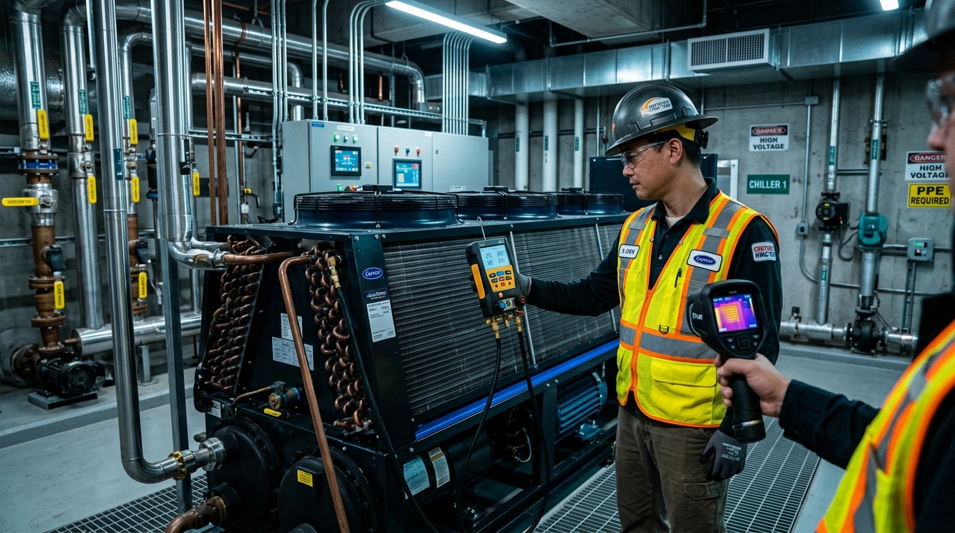
- Infrared Thermography: Conduct an annual thermal scan of the main power disconnect, motor terminal junction box, Variable Frequency Drive (VFD) DC bus capacitors, and starter lugs under full operating load. Any terminal displaying a ΔT greater than 10°F (5.5°C) above adjacent terminals indicates a high-resistance loose mechanical connection requiring re-torquing to manufacturer specifications.
Comprehensive Preventive Maintenance Matrix
To ensure seamless execution across facility operations teams, the following preventive maintenance matrix synthesizes operational frequencies, inspection tasks, targeted components, and strict engineering acceptance criteria:
| Frequency | Inspection Task | Target Component | Acceptance Criteria & Action |
|---|---|---|---|
| Daily | Log Operating Telemetry & Temperatures | Sensors, Microprocessor Display | Record entering/leaving chilled water temp, delta T (target 10°–12°F), suction/discharge pressures, and oil levels. Investigate any drift >5% from baseline. |
| Daily | Calculate Approach Temperatures | Evaporator & Condenser Bundles | Evaporator approach must remain ≤ 2.5°F; Condenser approach ≤ 3.0°F. An approach > 4.0°F requires tube inspection and cleaning scheduling. |
| Daily | Active BMS & Microprocessor Alarm Audit | Control Panel, Safety Loops | Verify zero active diagnostic warnings. Clear and log historical alarms (low suction, oil pressure differential, high motor temperature). |
| Monthly | Liquid Line Moisture Sight Glass Inspection | Filter-Drier, Sight Glass | Moisture indicator must display solid Green (Dry). If Yellow or Chartreuse, schedule filter-drier core replacement and leak detection. |
| Monthly | Hydronic Differential Pressure (ΔP) Audit | Evaporator / Condenser Water Loop | Measure differential pressure across bundle Pete's plugs. Verify flow rate holds at 2.4 to 3.0 GPM/ton per manufacturer pump curves. |
| Monthly | Inlet Air Filter & Trash Screen Cleaning | Air-Cooled Condenser Intakes | Inspect protective hail guards and mesh trash screens. Remove leaves, dirt, and airborne debris to prevent microchannel face starvation. |
| Monthly | Water Chemistry & Biocide Residual Verification | Closed Loop / Cooling Tower Sump | Closed loop pH 8.5–9.5; Molybdate 50–100 ppm; TDS < 1,500 μS/cm. Adjust automated chemical feed and biocide dosing pumps. |
| Semi-Annual | Microchannel Coil Wash & Fin Inspection | MCHE Aluminum Coils | Wash with ≤100 PSI water and pH-neutral cleaner (6.5–8.5) perpendicular to face. Straighten any bent fins with an aluminum fin comb. |
| Semi-Annual | Refrigerant Pinhole Leak Detection Audit | Braze Joints, Flanges, Reliefs | Execute heated-diode and ultrasonic sniffer survey. Target zero detectable leaks. Log all refrigerant additions per EPA 608 mandates. |
| Semi-Annual | Electrical Terminal Re-Torque & Visual Check | Starter, Contactors, Disconnect | De-energize and torque all power terminals to spec. Inspect contactor tips for carbon pitting; replace contacts if voltage drop > 0.15V. |
| Semi-Annual | Safety Relief Valve & Rupture Disc Check | Pressure Vessel Safety Devices | Verify zero corrosion or tell-tale gauge pressure on dual relief 3-way valves. Ensure relief discharge piping is free of water and obstruction. |
| Annual | Laboratory Lubricant Spectrometry & TAN Test | Compressor Oil Sump | Draw mid-sump oil sample for lab ICP-OES. TAN must be < 0.10 mg KOH/g; moisture < 50 ppm; wear metals (Fe, Cu, Al) within acceptable thresholds. |
| Annual | Compressor Motor Insulation Megger Testing | Stator Windings, Motor Terminals | Apply 500V/1000V DC for 60 seconds. Insulation resistance must exceed 5.0 MΩ (optimal > 50 MΩ). Values < 2.0 MΩ indicate winding failure risk. |
| Annual | Water-Cooled Condenser Tube Mechanical Brushing | Shell-and-Tube Heat Exchanger | Remove heads, mechanically brush internal copper tubes with nylon brushes to eliminate scale. Perform eddy current testing every 3–5 years. |
| Annual | Sensor Calibration & Transducer Verification | RTD Sensors, Pressure Transducers | Verify temperature thermistors in an ice/dry-well bath (±0.2°F accuracy). Calibrate pressure transducers against NIST-traceable digital master gauges. |
Troubleshooting Common Chiller Inefficiencies & Diagnostic Flow
When operating anomalies occur, technicians require a structured diagnostic logic flow rather than guesswork. The diagnostic matrix below addresses the four most common operational inefficiencies encountered in industrial chiller systems:
1. High Condensing Head Pressure
2. Low Suction Pressure & Freeze Trip
3. Elevated Evaporator Approach (> 4.0°F)
4. Motor Overcurrent & Voltage Imbalance
Summary: Engineering a Culture of Reliability
An industrial chiller is a precision thermodynamic machine whose operational life cycle should comfortably exceed 20 to 25 years. However, achieving maximum life expectancy while sustaining nominal design kW/ton ratings requires disciplined adherence to standardized maintenance routines. By enforcing rigorous daily approach temperature logging, implementing gentle, non-destructive cleaning protocols for aluminum microchannel coils, balancing hydronic loops to maintain 2.5 to 3.0 GPM per ton, and evaluating oil and electrical integrity via advanced spectrometry and Megger testing, plant engineers insulate their facilities against catastrophic breakdowns and eliminate unnecessary energy waste.